Hi
A musician collegue has been given a Fender Champ 15G guitar practise amp that doesn't work.
There's a couple of what I think are resistors on the amp board that appear to be burnt out.
They are labelled CR7 and CR8.
Just wondering if they would be easy to replace.
Would post a pic but doesn’t seem to be an attachment function.
Any help appreciated.
Fender Champ repair

Re: Fender Champ repair
https://imgur.com/
... is what you want...
they'll even give you a tag with with 'img' ids already affixed!
... is what you want...
they'll even give you a tag with with 'img' ids already affixed!
-
- Mike Stranks
Jedi Poster - Posts: 10586 Joined: Fri Jan 03, 2003 12:00 am

Re: Fender Champ repair
Those are diodes. So, yes, easy to replace if you know what they are. Normally printed on them, but if they are burnt-out you may not see the writing.
Last edited by Wonks on Tue Apr 09, 2019 6:21 pm, edited 1 time in total.

Reliably fallible.
Re: Fender Champ repair
They are 1N4003s. Cheap as chips (well, actually, cheaper).
https://www.thetubestore.com/lib/thetubestore/schematics/Fender/Fender-Frontman-15G-Schematic.pdf
But if they have burnt out, then something caused them to burn out, so there is probably something else that's failed.
https://www.thetubestore.com/lib/thetubestore/schematics/Fender/Fender-Frontman-15G-Schematic.pdf
But if they have burnt out, then something caused them to burn out, so there is probably something else that's failed.
Reliably fallible.
Re: Fender Champ repair
Wonks wrote:They are 1N4003s. Cheap as chips (well, actually, cheaper).
https://www.thetubestore.com/lib/thetubestore/schematics/Fender/Fender-Frontman-15G-Schematic.pdf
But if they have burnt out, then something caused them to burn out, so there is probably something else that's failed.
Many thanks.
Soldering them in shouldn’t be a problem but finding what caused them to burn out may be.
Re: Fender Champ repair
Wonks wrote:They are 1N4003s. Cheap as chips (well, actually, cheaper).
Are you sure? 1N4003's are usually black like the ones at the bottom of the picture. Those ones are more likely to be either small signal diodes or zener diodes (unless someone has previously fitted the wrong parts).
-

- James Perrett
Moderator -
Posts: 16388 Joined: Mon Sep 10, 2001 12:00 am
Location: The wilds of Hampshire
Contact:
JRP Music - Audio Mastering and Restoration. JRP Music Facebook Page
Re: Fender Champ repair
hmm, they LOOK like resistors assuming the painted lines on them mean anything. Maybe I should put on my readers. As the schematic indicates all the diodes are IN4003s, I think it's a bit odd. Maybe that's why it doesn't work! 
*edit the diagram indicates IN14448's unless otherwise indicated...and these look like resistors to my old out of practice eyes so maybe the prior work (if any) was done by someone like me
*edit the diagram indicates IN14448's unless otherwise indicated...and these look like resistors to my old out of practice eyes so maybe the prior work (if any) was done by someone like me
Last edited by Watchmaker on Tue Apr 09, 2019 9:12 pm, edited 2 times in total.
-

- Watchmaker
Frequent Poster - Posts: 1260 Joined: Wed Apr 13, 2016 12:00 am Location: Upstate NY, USA
Where does sound exist?
Re: Fender Champ repair
Hmm. Maybe I was seeing what I expected to see after reading the schematic and they are resistors. I've seen similar looking diodes though, which is what may have thrown me.
So maybe someone has had a go at modding the amp, and replaced diodes with resistors?
Or maybe I've got the wrong amp schematic.
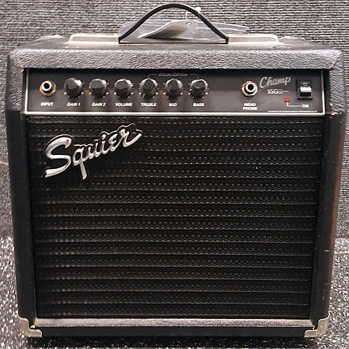
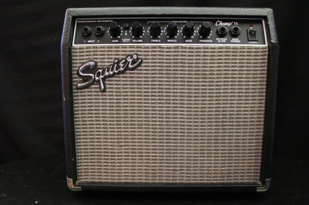
Is it a Fender Frontman or a Squier Champ. because there are 15G models of both? But the Squier Champ schematic I found (from 1985) called the diodes D, not CR, so I'm leaning towards the schematic I found. It may help if you can see a model number on the back of the amp.
So maybe someone has had a go at modding the amp, and replaced diodes with resistors?
Or maybe I've got the wrong amp schematic.
Is it a Fender Frontman or a Squier Champ. because there are 15G models of both? But the Squier Champ schematic I found (from 1985) called the diodes D, not CR, so I'm leaning towards the schematic I found. It may help if you can see a model number on the back of the amp.
Reliably fallible.
Re: Fender Champ repair
1N4742 are zener diodes, whereas the 1N4003 is a standard diode.
But a subsequent PCB layout that goes with the diagram I found shows a very different layout for the components compared to the photo. So it's almost certainly the wrong schematic. So those zeners may very well be correct.
A model number and/or photos of front and back of the amp will help.
But a subsequent PCB layout that goes with the diagram I found shows a very different layout for the components compared to the photo. So it's almost certainly the wrong schematic. So those zeners may very well be correct.
A model number and/or photos of front and back of the amp will help.
Reliably fallible.
Re: Fender Champ repair
They look like diodes to me, not resistors, and the PCB component idents tie in with the schematic -- although the schematic linked above is for a Frontman amp rather than a Champ... So there may well be aome sifferences. For example, the schematic says those components should be part of the power supply rectifier bridge, yetbthose shown in the photo look like small signal diodes... so some further careful checking is required to confirm the schematic and board really do tally, and that the diodes are what they are supposed to be!
The circuitry doesn't look too complicated, so it shouldn't be too hard to sketch it out if necessary.
But can I ask what make the OP (or OP's friend) think they are burnt-out resistors?
Start from the basics... Does the Champ's power LED illuminate?
Has anyone measured the PSU output voltages?
Some logical, progressive, fault-finding is required here, but there's nothing complicated in the circuitry and nothing difficult for an experienced tech to diagnose and fix...
Start with the low-tension side of the mains transformer's AC voltage going into the PSU, then if that's okay, the high (+/-23?) and low (+/-15?) DC volts coming out from the PSU, and then confirm present as appropriate at each of the gain stages, and at the muting FET at the input of the power amp chip (assuming its presence).
If the DC power conditions are correct, then check the signal flow through the gain stages from input to output... A web search suggests the volume pots are known to fail.
The schematic gives expected signal levels at each stage from a 5mV input (-43dBu), so it should be easy to inject a tone and follow it through the signal path.
Last edited by Hugh Robjohns on Tue Apr 09, 2019 11:53 pm, edited 6 times in total.
-

- Hugh Robjohns
Moderator -
Posts: 42816 Joined: Fri Jul 25, 2003 12:00 am
Location: Worcestershire, UK
Contact:
Technical Editor, Sound On Sound...
(But generally posting my own personal views and not necessarily those of SOS, the company or the magazine!)
In my world, things get less strange when I read the manual...
(But generally posting my own personal views and not necessarily those of SOS, the company or the magazine!)
In my world, things get less strange when I read the manual...
Re: Fender Champ repair
Yes Hugh, if that schematic is the right one the diodes are part of the bridge PSU and some systematic checking is required.
I suspect the TDA 2050 output chip might have shorted, look for blown fuses.
The diodes may not have failed, just got bloody hot! The diodes are rated at 1A which would be more than adequate for "hi fi" use but if that amp has been ragged to the limit, especially into a 4 Ohm speaker, they will have run hot.
If the power chip has failed it will need some good PCB soldering skills to remove it as the pads are small and quite closely packed, print can easily be lifted. Then the new IC will need thermal compound properly applied. Check the Zobel network on the output is intact and correct.
Dave.
Re: Fender Champ repair
Wonks wrote:THE SCHEMATIC IS THE WRONG ONE FOR THAT AMP!
HTH.
Odd because I have just had a reply from a very good amp tech at frets who gave me a link to the very same?
We need a nameplate then.
Dave.
Re: Fender Champ repair
ef37a wrote:Odd because I have just had a reply from a very good amp tech at frets who gave me a link to the very same?
Yes, it's because it's the first one that comes up in google when you search for a Champ 15G schematic.. but it's actually the Frontman 15 instead... I made the same mistake as Wonks until I looked closer at the drawing details in the bottom right-hand corner...
Having said that, I dare say the two are similar in general circuit outline, even if the component naming on the PCB is different.
It appears that the correct schematics can be ordered from Fender themselves:
https://support.fender.com/hc/en-us/art ... y-Archives
H
-
- Hugh Robjohns
Moderator -
Posts: 42816 Joined: Fri Jul 25, 2003 12:00 am
Location: Worcestershire, UK
Contact:
Technical Editor, Sound On Sound...
(But generally posting my own personal views and not necessarily those of SOS, the company or the magazine!)
In my world, things get less strange when I read the manual...
(But generally posting my own personal views and not necessarily those of SOS, the company or the magazine!)
In my world, things get less strange when I read the manual...
Re: Fender Champ repair
Reliably fallible.
Re: Fender Champ repair
I found this as a possible schematic:
https://music-electronics-forum.com/attachment.php?attachmentid=3932&d=1230346488
https://music-electronics-forum.com/attachment.php?attachmentid=3932&d=1230346488
-
- Hugh Robjohns
Moderator -
Posts: 42816 Joined: Fri Jul 25, 2003 12:00 am
Location: Worcestershire, UK
Contact:
Technical Editor, Sound On Sound...
(But generally posting my own personal views and not necessarily those of SOS, the company or the magazine!)
In my world, things get less strange when I read the manual...
(But generally posting my own personal views and not necessarily those of SOS, the company or the magazine!)
In my world, things get less strange when I read the manual...
Re: Fender Champ repair
There seem to be several different possible solid-state designs, some with a chip amp, some with a discrete transistor amp... but none are complicated from what I've seen and should be easy to fault-find by a competent tech.
H
H
-
- Hugh Robjohns
Moderator -
Posts: 42816 Joined: Fri Jul 25, 2003 12:00 am
Location: Worcestershire, UK
Contact:
Technical Editor, Sound On Sound...
(But generally posting my own personal views and not necessarily those of SOS, the company or the magazine!)
In my world, things get less strange when I read the manual...
(But generally posting my own personal views and not necessarily those of SOS, the company or the magazine!)
In my world, things get less strange when I read the manual...