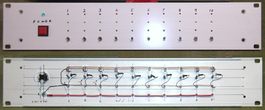
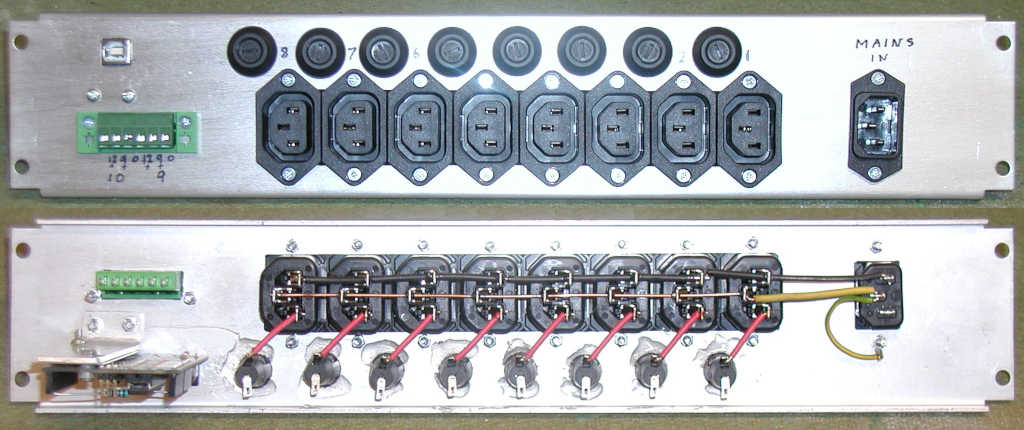
Now I have a soldering iron again I can get on with this

The start and stop circuit has proved to be an iterative design! The final schematic being this:
www.musically.me.uk/Switcher/Start-Stop.pdf
Q2, Q3 and the associated parts act as a very basic switch that can have only one of the transistors 'on'. This particular circuit is a simplified Schmitt trigger.
In our case we want to ensure that Q3 always switches on when power is applied, and that when a trigger pulse is applied to Q2 this switches on, and remains on, at least until the supply voltage has dropped too low for the relay to be powered.
This 'on' state is guaranteed by C2 holding Q2 base at zero for a while. By the time it has charged Via R4, Q3 is well and truly on, and drawing enough current to raise the voltage across R7 such that Q2 needs an external 'boost' to be able to change this. MR1 is only there to ensure a stable voltage at this point.
Sending a pulse via R1 pulls up the voltage on Q2 base enough for it to conduct and rob Q3 of base current. The state now rapidly changes, assisted by the fact that Q2 draws much less current than Q3 so the voltage across R7 drops sufficiently to ensure Q2 stays on. D1 ensures that when the pulse ends, it can't pull Q2 off again.
Now I extensively tested this every way I could think of before installing it, and it worked perfectly... Only when wired in it didn't! Switch on was fine. Press button, power comes up, relay clicks over and keeps the mains connected. However, trigger switch off and yes, relay clicks over, then a short while later switches back! WTF!!!
This took a while to understand. First off, at the time the relay disconnected, the only thing that was drawing any current at all was Q2 - a whole 2mA, so the voltage from the PSU faded down in a distinctly leisurely manner. Also, it hiccuped. This briefly robbed Q2 of power, switching it off, then rose enough for Q3 to engage.
My first attempt at resolving this, was the addition of Q4 and R9. When the relay turns off, the voltage at the transistor end rises to the rail voltage, dragging up the base of Q4 with it, and hence to 'top' end of R9. This now draws about 250mA, which is enough to discharge the PSU caps pretty quickly. This solved the problem most of the time, but was not a complete solution.
My next thought was to find a way to maintain the supply to Q2 while the main supply was falling. This function is provided by C3 and D2. The switch off is now quite stable. R8 is only there to limit the surge through D2 as the power comes up and C3 charges.
Finally, Q1 is quite separate from all of this, and is there to send a switch off signal to the Arduino. This happens as the second pole of the Start/Stop switch opens. The very high values of R10/R11 are chosen to limit current to a safe level, should the switch fail catastrophically shorting to the mains side - I never completely trust 2 pole switches where one side is mains, and the other side is supposedly isolated.
As mentioned previously, the Arduino will only respond to switch off if it occurs when all the start up enable steps have been completed.

