Is this a mains power sequential switcher?
Programmable Sequential Switch

Re: Programmable Sequential Switch
Indeed it is. It also jumps through significant steps regarding safety, which I'll describe in more detail nearer completion.
-

- Folderol
Forum Aficionado -
Posts: 20648 Joined: Sat Nov 15, 2008 12:00 am
Location: The Mudway Towns, UK
Contact:
Seemingly no longer an 'elderly'.
Now a 'Senior'. Is that promotion?
Now a 'Senior'. Is that promotion?
Re: Programmable Sequential Switch
I think it's all explained in the very first post. It turns everything in the studio on (including the computer) using a single switch, with each of eight outlets powering devices in the correct sequence and with the appropriate timing to ensure everything comes up at the right moment.
And it can also turn everything off again, in a similar sequenced procedure.
All this automation is courtesy of an Arduino to control the sequencing and to negotiate with the computer, plus some custom circuitry to activate and monitor the mains relays etc.
And it can also turn everything off again, in a similar sequenced procedure.
All this automation is courtesy of an Arduino to control the sequencing and to negotiate with the computer, plus some custom circuitry to activate and monitor the mains relays etc.
-

- Hugh Robjohns
Moderator -
Posts: 43427 Joined: Fri Jul 25, 2003 12:00 am
Location: Worcestershire, UK
Contact:
Technical Editor, Sound On Sound...
(But generally posting my own personal views and not necessarily those of SOS, the company or the magazine!)
In my world, things get less strange when I read the manual...
(But generally posting my own personal views and not necessarily those of SOS, the company or the magazine!)
In my world, things get less strange when I read the manual...
Re: Programmable Sequential Switch
Makes sense. I have a Furman that does this in four stages. I would love to add another for my synths.
Though I'm afraid that first post goes way over my head!
Though I'm afraid that first post goes way over my head!
An Eagle for an Emperor, A Kestrel for a Knave.
Re: Programmable Sequential Switch
Sorry. I do try to make what I write a comprehensible as possible, but it's extremely difficult to know what knowledge level to target.
Thanks for stepping in Hugh.
Thanks for stepping in Hugh.
-
- Folderol
Forum Aficionado -
Posts: 20648 Joined: Sat Nov 15, 2008 12:00 am
Location: The Mudway Towns, UK
Contact:
Seemingly no longer an 'elderly'.
Now a 'Senior'. Is that promotion?
Now a 'Senior'. Is that promotion?
Re: Programmable Sequential Switch
An Eagle for an Emperor, A Kestrel for a Knave.
Re: Programmable Sequential Switch
I know what you are doing, why you are doing it and pretty much understand the electronics too, but reading your initial descriptions and Hugh's explanation my mind keeps on conjuring images of a Heath Robinson cartoon of a device with much knotted string, pulleys gears and governors linking sequential paddles on a shaft with little mallets thwacking down on a row of push button dome switches 
Re: Programmable Sequential Switch
You've seen Arpangel's version, then? 
-
- Hugh Robjohns
Moderator -
Posts: 43427 Joined: Fri Jul 25, 2003 12:00 am
Location: Worcestershire, UK
Contact:
Technical Editor, Sound On Sound...
(But generally posting my own personal views and not necessarily those of SOS, the company or the magazine!)
In my world, things get less strange when I read the manual...
(But generally posting my own personal views and not necessarily those of SOS, the company or the magazine!)
In my world, things get less strange when I read the manual...
Re: Programmable Sequential Switch
First of all, I've run a complete test of the mains channels being timed by the Arduino, and they all behave quite correctly. At this point I still hadn't built the sensing kit for the DC outputs, so although the relays clicked over correctly, there was no indication.
With that out of the way I got on with finalising the DC stuff, however I had a really puzzling problem with these for a while. There just a handful of components that I put on a small carrier board. This is not stripboard, but has a pattern of holes, with pads, which is very convenient for just nine components. Wired up and double-checked the wiring, but when powered up, neither of them recognised a load on the output
After another visual check, confirming everything was correct, I started measuring voltages. These didn't make any sense at all, so next it was cold checks with a meter. Both rectifier diodes showed as short circuit - these are 3A jobbies that couldn't possibly draw more than an amp where they were fitted. It took a while to get round to disconnecting one of the diodes after eliminating everything else I could think of. The diode was perfectly OK, and the S/C was on the board itself.
One trick I employ on really weird faults is to draw out exactly what is there, totally disregarding any schematics. It is surprisingly easy to repeatedly make the same mistake, especially when looking at two sides of a board. Well, that didn't help. The drawing matched exactly.
Eventually, and with some reluctance I considered there might be a problem with the board itself, thinking I might have made solder bridges somewhere, so out came the magnifying glass and a strong light. It was still some time before I spotted some extremely fine traces (less than a hair's width) between some of the pads on the edges of the board. I confirmed that these also were present on the part of the board I hadn't needed and had cut off. The pads are gold plated, and I'm guessing that the temperature of the board edges was fractionally too low. With those broken everything worked correctly.
I'm now on the home straight - I have some tidying up to do, before I do the final write-up and post a picture of the complete innards, and then the software to install on my DAW machine.
-
- Folderol
Forum Aficionado -
Posts: 20648 Joined: Sat Nov 15, 2008 12:00 am
Location: The Mudway Towns, UK
Contact:
Seemingly no longer an 'elderly'.
Now a 'Senior'. Is that promotion?
Now a 'Senior'. Is that promotion?
Re: Programmable Sequential Switch
I use a panel of switches operating solid-state relays... and a finger! 

-
- Hugh Robjohns
Moderator -
Posts: 43427 Joined: Fri Jul 25, 2003 12:00 am
Location: Worcestershire, UK
Contact:
Technical Editor, Sound On Sound...
(But generally posting my own personal views and not necessarily those of SOS, the company or the magazine!)
In my world, things get less strange when I read the manual...
(But generally posting my own personal views and not necessarily those of SOS, the company or the magazine!)
In my world, things get less strange when I read the manual...
Re: Programmable Sequential Switch
Hugh Robjohns wrote: ↑Thu Jan 13, 2022 9:59 pm I use a panel of switches operating solid-state relays... and a finger!
Pah! Philistine
-
- Folderol
Forum Aficionado -
Posts: 20648 Joined: Sat Nov 15, 2008 12:00 am
Location: The Mudway Towns, UK
Contact:
Seemingly no longer an 'elderly'.
Now a 'Senior'. Is that promotion?
Now a 'Senior'. Is that promotion?

Re: Programmable Sequential Switch
The switcher is now installed with everything now working correctly, although I hadn't realised just how long it takes the computer to fully initialise and start all the software. This is nearly a minute, and I'd only allowed for 30 seconds on the switcher's timers. Fortunately this is just long enough to ensure nothing conflicts. I'll probably change it later though to allow for any future additions.
Anyway, here is the promised view of the insides.
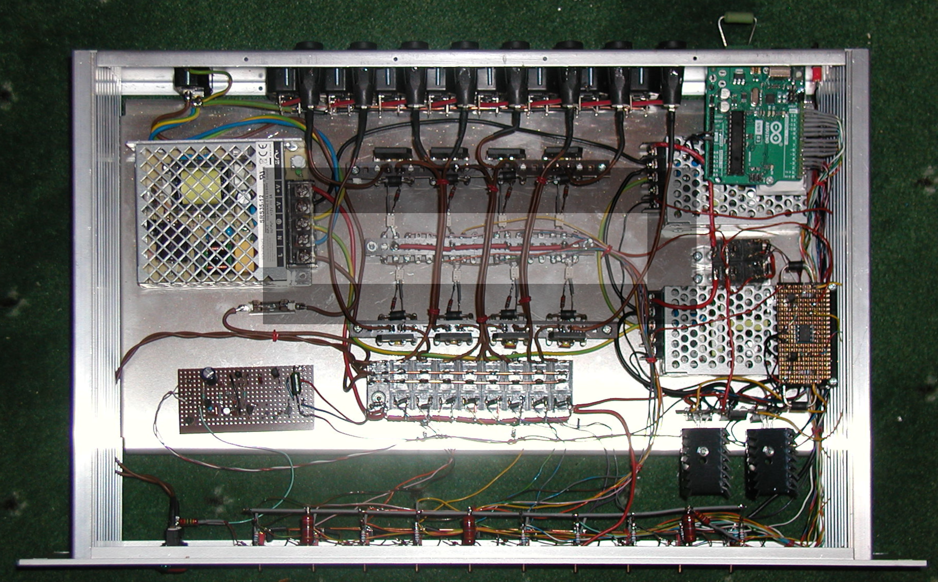
Top left, just below the mains input socket is the DC power supply. It's fuse is immediately below it - if this should ever blow, there's a serious problem, so it's not a 'user serviceable' part! Below this is the startup PCB, and to the right of this are the AC control relays. The first one being for the PSU itself.
Top right, you can see a resistor stuck in one of the DC output sockets I was using for testing, then there's the Arduino. The leads coming out on the right hand side have diodes hidden under the sleeving - part of the Wonks Mod. Alongside this is the Wonks Mod switch Half hidden is the DC/DC converter for channel 9, then there are the two DC control relays, and below that the Ch. 10 DC/DC converter, on top of which is the board with both current sense circuits. By shear chance, it works out that the sense threshold for both AC and DC output is with about a 1W load.
Below this are three 9V regulators. The two outside ones are for the 9V outputs, and have large heatsinks - only really needed if the output is shorted. The central one feeds the Arduino.
Along the bottom attached the the front panel, you can see the rest of the Wonks Mod. The grey wire supported by three 10M resistors has diodes going to each channel enable line so they can all be turned on. The only function those resistors serve is to act as convenient supports!
All of this is fairly benign stuff. The scary bit is the three tagstrips in the middle of the chassis. Ideally this would all be on a nice fibreglass PCB, but I don't have the facilities to produce such a thing with mains rated track distances and isolation slots under the optocouplers. Therefore I've fallen back to old-fashioned point-to-point wiring on tagstrips. Only the two outer ones have mains voltages on them and you'll notice I've spaced the channels out leaving a missing tag between them. The voltage across and rectifier assembly is never more than about 2.5V but the voltage between the channels can be full mains, depending on which ones are active.
It's not possible to get wire-ended optocouplers, so I've had to cheat and straighten the legs out, soldering them directly to tags on the low voltage centre tagstrip, and adding one short leg extension and a resistor directly on the mains side.
You'll notice I've dressed all the wiring away from the rectifiers (the couple going over the top of two are actually well above them). At maximum possible output, each individual rectifier assembly can dissipate just over 7 watts of heat. However, as the mains input is rated at 13A, the total for all 8 is about 30W. That's still quite lot of heat to get rid of. The way I'll be dealing with this will be to mount an earthed thin metal plate over the central area, supported by the two studs sticking up from the ends of the middle tagstrip. This won't quite reach the the rectifiers (the darker shaded area in the picture). Then I'll drill a pattern of holes in the top cover, just above this plate(the lighter inner area). The airflow will then be in through front bottom, up over the rectifiers then back over the plate to the top vent holes. This resolves both heat and safety issues.
Anyway, here is the promised view of the insides.
Top left, just below the mains input socket is the DC power supply. It's fuse is immediately below it - if this should ever blow, there's a serious problem, so it's not a 'user serviceable' part! Below this is the startup PCB, and to the right of this are the AC control relays. The first one being for the PSU itself.
Top right, you can see a resistor stuck in one of the DC output sockets I was using for testing, then there's the Arduino. The leads coming out on the right hand side have diodes hidden under the sleeving - part of the Wonks Mod. Alongside this is the Wonks Mod switch
Below this are three 9V regulators. The two outside ones are for the 9V outputs, and have large heatsinks - only really needed if the output is shorted. The central one feeds the Arduino.
Along the bottom attached the the front panel, you can see the rest of the Wonks Mod. The grey wire supported by three 10M resistors has diodes going to each channel enable line so they can all be turned on. The only function those resistors serve is to act as convenient supports!
All of this is fairly benign stuff. The scary bit is the three tagstrips in the middle of the chassis. Ideally this would all be on a nice fibreglass PCB, but I don't have the facilities to produce such a thing with mains rated track distances and isolation slots under the optocouplers. Therefore I've fallen back to old-fashioned point-to-point wiring on tagstrips. Only the two outer ones have mains voltages on them and you'll notice I've spaced the channels out leaving a missing tag between them. The voltage across and rectifier assembly is never more than about 2.5V but the voltage between the channels can be full mains, depending on which ones are active.
It's not possible to get wire-ended optocouplers, so I've had to cheat and straighten the legs out, soldering them directly to tags on the low voltage centre tagstrip, and adding one short leg extension and a resistor directly on the mains side.
You'll notice I've dressed all the wiring away from the rectifiers (the couple going over the top of two are actually well above them). At maximum possible output, each individual rectifier assembly can dissipate just over 7 watts of heat. However, as the mains input is rated at 13A, the total for all 8 is about 30W. That's still quite lot of heat to get rid of. The way I'll be dealing with this will be to mount an earthed thin metal plate over the central area, supported by the two studs sticking up from the ends of the middle tagstrip. This won't quite reach the the rectifiers (the darker shaded area in the picture). Then I'll drill a pattern of holes in the top cover, just above this plate(the lighter inner area). The airflow will then be in through front bottom, up over the rectifiers then back over the plate to the top vent holes. This resolves both heat and safety issues.
-
- Folderol
Forum Aficionado -
Posts: 20648 Joined: Sat Nov 15, 2008 12:00 am
Location: The Mudway Towns, UK
Contact:
Seemingly no longer an 'elderly'.
Now a 'Senior'. Is that promotion?
Now a 'Senior'. Is that promotion?
Re: Programmable Sequential Switch
VERY neat wiring Will - I'm most impressed! 
-

- Martin Walker
Moderator -
Posts: 22441 Joined: Wed Jan 13, 2010 8:44 am
Location: Cornwall, UK
Contact:
Re: Programmable Sequential Switch
That is very tidy. 
And I almost understood what you were talking about as well!
And I almost understood what you were talking about as well!
-

- Drew Stephenson
Apprentice Guru -
Posts: 29432 Joined: Sun Jul 05, 2015 12:00 am
Location: York
Contact:
(The forumuser formerly known as Blinddrew)
Ignore the post count, I have no idea what I'm doing...
https://drewstephenson.bandcamp.com/
Ignore the post count, I have no idea what I'm doing...
https://drewstephenson.bandcamp.com/
Re: Programmable Sequential Switch
That's art and science!
-

- Eddy Deegan
Moderator -
Posts: 9887 Joined: Wed Sep 01, 2004 12:00 am
Location: Brighton & Hove, UK
Contact:
Re: Programmable Sequential Switch
Thanks Guys.
I must admit this was rather a rushed job - it only took about three years from start to finish
I must admit this was rather a rushed job - it only took about three years from start to finish
-
- Folderol
Forum Aficionado -
Posts: 20648 Joined: Sat Nov 15, 2008 12:00 am
Location: The Mudway Towns, UK
Contact:
Seemingly no longer an 'elderly'.
Now a 'Senior'. Is that promotion?
Now a 'Senior'. Is that promotion?
Re: Programmable Sequential Switch
Currently standing at a sniff under £250, but I need go through and sort out what I bought against what I actually used, and the value of what I already had.
Slave labour, so no costs there
Slave labour, so no costs there
-
- Folderol
Forum Aficionado -
Posts: 20648 Joined: Sat Nov 15, 2008 12:00 am
Location: The Mudway Towns, UK
Contact:
Seemingly no longer an 'elderly'.
Now a 'Senior'. Is that promotion?
Now a 'Senior'. Is that promotion?
Re: Programmable Sequential Switch
I'm really interested in getting into Arduino projects.
I'm interested in what development environment people are using, loading the code in to the device etc?
I'm interested in what development environment people are using, loading the code in to the device etc?