If anyone’s interested in how easy it is to install a multi-piezo disk type pickup into an acoustic guitar, here’s how I did it on my Atkin OM37.
Here's the full kit to install; a K&K Pure Mini pickup system with the optional volume control:
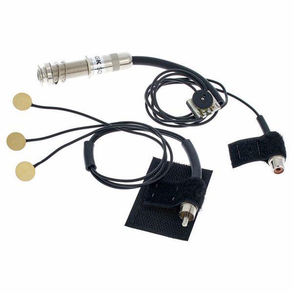
For ease of installation it comes in two parts; the three piezo disks wired to an RCA style plug and the volume control and output pin jack wired to an RCA socket.
The first step is to assemble the simple piezo locating jig as you need to glue a rod through a plate (see the later description for more details).
The second step was to fit the new endpin jack. The existing Atkin endpin strap button was just wedged in place; a tapered button fitting into a tapered hole, so was easy to remove as it just pulled out after twisting. Whilst the hole went all the way through the end block, it was far too small to fit the jack in, being about 8mm in diameter at the outer end and tapering to about 4mm.
Whilst K&K recommend a drill diameter of ½”, I measured the jack barrel and found it to be 11.8mm in diameter, so I planned to use a 12mm drill as the final stage of enlargement. K&K recommend using increasing sizes of self-centring drill bits rather than going straight to the size wanted, so I followed their recommendation.
To avoid chipping the finish on the guitar, I first used a hand reamer to enlarge the external hole diameter to just over 12mm. This still left me with a tapered hole (albeit larger) and which allowed me to use 10mm, 11mm and then a 12mm drill bit to gradually enlarge the hole diameter, whilst always keeping the area the drill was cutting into below the surface of the guitar body, so the drill edges wouldn’t catch the nitro finish.

Even so, the drills tended to catch in the wood, (I was using a battery hand-drill) so some initial reverse drilling was first required to allow me some space to then get the drill up to speed in the outer end of the hole before applying it to the wood.
I then tested the hole size by fitting the barrel jack from the outside, and found it slightly too snug at the inner end of the hole, so widened it out slightly further with a round file until it was an easy fit but with minimal play.
Up to this point I’d left the strings on, but now I needed access through the sound hole, so I fitted a capo on the 2nd fret, loosened all the strings, pulled the bridge pins out, freed the string ends and moved them out the way (the strings were almost-new D’Addario XS coated strings so were too good to take off and replace).
Drilling had left a lot of sawdust inside the guitar, so a mixture of vacuum cleaner and guitar shaking got rid of that.
The next step was to adjust the internal barrel nut so that just enough of the barrel poked out the hole so that with the external nut on, the end of the barrel either sat level with, or was slightly proud of the screw-on end-piece strap button. If the end-of-barrel thread sits below the level of the strap button, then the jack can’t be inserted far enough into the barrel for good contact to be reliably made with the spring connections. I’ve fixed a few electro-acoustics that kept cutting out in use, by simply adjusting the amount of thread poking out of the body so the end was slightly proud of the strap button.
Here you can see the profile of the barrel jack. The silver cover on the left screws on to the barrel and both helps lock the internal nut in place once it’s positioned and protects the electrical contacts on the jack. Note that this is a standard size-barrel jack, so if you wished to change the pickup system at a later date, there shouldn’t be any further drilling requirement (at least for the jack).

I have a long-shafted Phillips screwdriver which is of just the right diameter to fit into the barrel jack and be gripped by the contacts to hold the jack in place on the end of the screwdriver. Feeding the screwdriver all the way through the hole made it easy to then place the barrel jack on the end and pull it back through the hole in a seconds.
If your hands and wrists are small enough, you can do it all by feel and holding the barrel jack in your fingertips, but it’s fiddly and can be quite painful, so a long stock of some kind that fits into the jack and can be gripped make it a lot quicker and easier. Especially when you’ll probably have to do it several times in order to get just the right amount of thread protruding from the hole. Don’t forget to fit the internal solid washer and locking star washer on the barrel when fixing the internal nut position otherwise you’re liable to then have too little thread projecting.
It's then a matter of screwing the internal jack connection cover onto the barrel (as it’s pre-wired there’s no danger of forgetting to fit it before soldering the wires to the jack), fitting the jack into the hole one last time and fitting the external washer and screw. If you look back at the barrel jack profile picture, you should see that there are two holes in the end of the thread for putting something through to stop the jack rotating when doing up the external nut. If you use this, it’s best to use a low-profile spanner (I bought a set just for this type of application) as there’s not a lot of space between the holes and the body.
Once all is nice and tight (but not over-tight as you run the risk of cracking the finish), you can then screw the end strap-button on, leave the other end of the output cable inside the guitar and take a short breather.

It's now time to glue the piezo disks in place. I say glue as this is what K&K recommend, though double-sided tape is another option (and some tape is provided in the kit) though it’s less permanent and K&K say it doesn’t provide as good sound transmission to the disks as glue. The recommended glue is superglue gel. This has enough viscosity to stay put on the disk whilst it’s manhandled into place without dropping off onto the body finish or the internal woodwork. It also has a reasonable working time, so won’t dry before you’ve got the disk in place.
K&K provide a small jig to help you with locating the disks in the correct place, consisting of a clear plastic plate (well it’s really clear if you take the protective plastic off both sides), a plastic rod that needs to be glued in place roughly 1/3 below and 2/3 above the plate so that the rod can be used both as a handle and as a locating device when passed through a string hole in the bridge. It’s easiest to put this together before you do anything else. I used the same CA/superglue gel that is used for the disks.
A golf tee is also provided as a second locating pin, which remains free and is used from the top of the guitar bridge only.
K&K provide location details for the three disks. Basically, they need to be positioned along the line of the saddle, in-between pairs of strings. Whilst the low E and A, and D and G strings pairs should have the disks located centrally, on the B and high E pair, the disk is best offset towards the high E string.
The disks are positioned and glued one at a time. The individual leads to each disk are fairly long and allow you to work with disks both in and out of the guitar body at the same time. A loose piece of sleeving allows you to slide it up towards the disks and gather the leads into a tidy group once all the disks are in place.
For each disk, the first job is to locate the correct position for the disk from the top of the bridge. This should make it obvious why the plastic plate is clear: so that you can see the saddle beneath it to centre the disk on the saddle and between the string holes.

You can see above that I’ve used the golf tee from underneath the bridge, but this was really for clarity in this photo. I subsequently used it from the top (as seen in other photos). A strip of a BluTac-like substance is provided to allow you to stick the disk in place on the jig. You only need a small bit; smaller than the disk but thick enough to raise the disk away from the jig plate as the connection point of the lead to the disk isn’t flat so the disk needs a bit of clearance space from the plate so it will sit parallel to the plate.
Here we have a disk sitting on its BluTac positioned on the saddle line and between the low E and A strings:

Then we add a reasonable amount of superglue gel to the disk, prior to sticking it on the underside of the bridge block. You want more than the barest scrape of glue as K&K state that insufficient glue is the most common cause of installation issues.

Then it’s a process of carefully moving the jig to the inside of the guitar, poking the upright rod through the correct string hole, putting the golf tee down through an appropriate hole to fully line up the plate and then push the plate up from underneath and hold in place for around 30 seconds for the superglue gel to start curing.

After that you leave the plate in place for the glue to cure further for about 5 minutes. Look ma, no strings!

Then you simply push/pull the plate away, leaving the piezo disk in place. Repeat for all three disks and slide that bit of sleeving up the three leads towards the disks so there’s less to flap around inside.
Connect the two halves of the RCA connector, stick the Velcro flaps together to hold the RCA connector together so it won’t vibrate loose, then peel the protective plastic off the back and stick it to the inside of the guitar.

Likewise peel off the plastic from the rear of the volume control wheel and stick that to a suitable cross-member. I stuck mine so that it can be easily felt by running your finger under the rim of the sound hole where there’s a wide bit of flat bracing, but can’t be seen from the front.
Now you see it…

Now you don’t…

After that it was just a case of using some of the supplied sticky-backed cable clips to gather the loose cables up inside, restring and retune the guitar and plug it all in.
Overall installation time was around an hour including de-stringing and re-stringing. I have done this once before, so knew all the steps. Even so, it probably took less time the first time as the guitar (an Avalon Legacy D25) had the correct end pin/barrel jack hole size straight from the factory.
It really is all straightforward and apart from having the correct sized drill bits (you could do without the reamer if you wanted to), you don't need any specialised tools at all.
So that’s it for the installation.
The Sound
It was all going so well up until this point. On the Avalon, the sound was great (with a bit of EQ tweaking) just plugged into my Fishman Loudbox Mini.
The Atkin sounds very bassy and lacks treble. I can boost the treble and cut the mid and bass control right back to get a useable, if not particularly great sound. It is very feedback resistant though and I hardly get any string squeak noise when moving my fingers up and down the strings. Plenty of volume from all the strings though, so it’s not that the disks aren’t sticking or anything. I’m currently putting it down to the construction of the Atkin and maybe a thicker than normal under-bridge block or something.
K&K do say that their pickups don’t like to feed into too high an input impedance (which makes the sound bassy), ideally between 500k to 1 Meg ohms, and the Fishman has a 10 Meg input impedance.
But, this pickup has the volume control fitted. I measured the pot resistance before fitting it and it was 840k. So put that in parallel with a 10Meg impedance and you get an equivalent 775k input impedance, which should be fine.
I also tried it with a buffered pedal with a 1 meg input impedance, which should give an equivalent 456k input impedance, but with no difference in sound. I have yet to try it into the line input on my small mixer, as I have the mixer but the power supply has temporarily gone missing (this is what happens when you are made to tidy up!). The input impedance on this should be 47k or less (Alesis don’t publish a figure) so that may give some improvement as it’s quite a big drop.
Playing with the amp EQ gave me the idea to try some of my EQ pedals with it, but I first decided to try my early 1980s Pearl TH-20 Thriller pedal with it, and it’s excellent!
It's a combination of a high pass filter, six resonant peak filters with adjustable resonance, and a blend control mixing the effected and straight-through signal amounts.

The frequency control determines the cut-off of the high pass filter, ‘color’ controls the filter resonance level (I assume, as turning it up high you can get the pedal to self-resonate). And ‘Multipeak’ seems to determine the amplitude of the resonant filters (which may itself be a blend control – the original Pearl knob descriptions are very vague).
It allows me to cut the bass and low middle frequencies considerably via use of the high pass filter setting and blend control, and the colour and multipeak controls add in some useful treble.
I’d prefer not to use the pedal, but a lot of people use preamp pedals to tailor their acoustic sound or use both the onboard preamp and amp/PA EQ in order to get a decent tone, so I’m not too concerned.


