I think I know what could be going on. I could be more certain if I could find a proper circuit diagram for the interface, but I can't.
The only thing that all the inputs have in common is their ground/sleeve connection. Therefore it
must be to do with that, and some of the signal from one input leaking through to another input via that ground path.
My idea of how this could occur depends on:
A) The sleeve connections on all the TRS/XLR inputs being connected to a common ground plane/track on the PCB not being directly connected to the system 0v reference at some point, and...
B) The line/hi-Z switch acting rather like this one in a Mackie mixer (this is
not the UR242 block schematic):
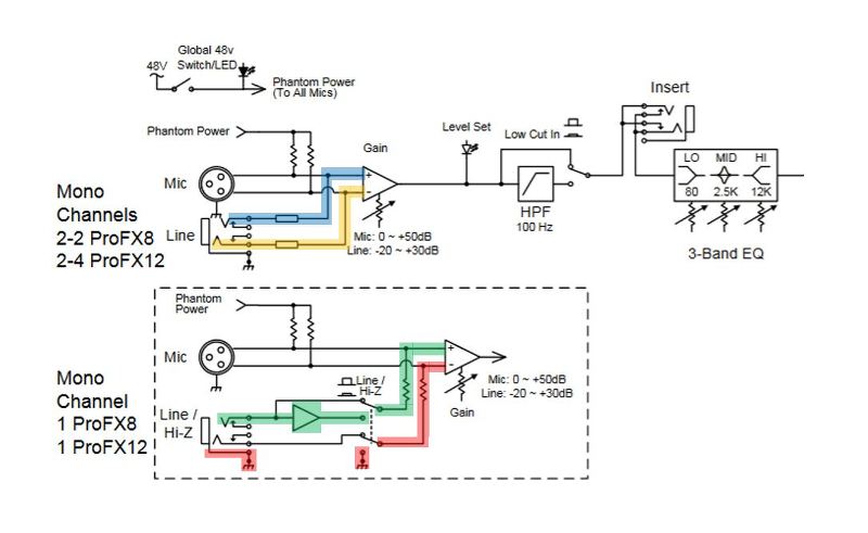
...where a high impedance input op-amp is put in series with the positive T (tip) input input signal to both increase the input impedance and to also boost the guitar level signal up to line level.
But the R (ring) connection is also connected to the system 0v rail as well as ground when the Hi-Z switch is operated.
I would normally have expected that the ground rail would be connected to 0v at a single point, probably right at the unit's input power connector, to equalize the potentials. Maybe there is no direct connection at all though but possibly a link via a capacitor so that any potential DC current is blocked. Or it may be that there is one direct connection at the input power socket (these power sockets often have two pins for ground/0v connections) but the solder joint is poor or cracked and relatively high resistance, maybe a few ohms.
Both the above would allow for there to be a small resistance between the ground track and 0v. Keep that in mind.
With only one input having a TS jack inserted, the other inputs' T and R connections remain unconnected so there is no obvious signal bleed.
But plug in a TS jack to another input and the sleeve of the jack connects the R and S connections of the jack together, so the negative side of the differential input is now connected to the UR242 ground potential.
With a TS jack input, you would normally expect this negative input to be held firmly at a constant 0v. But if the ground to 0v connection has some measurable resistance, then the whole ground track can be raised in potential very slightly if another TS input has a signal on it, and the negative input (R) connection of this jack with no input signal will see a very low level version of the signal appearing. The positive (T) connection of the input sees nothing, so the differential input outputs a low-level, polarity reversed signal, which is what you see.
If you plugged in an XLR cable or a TRS jack, the R and S connections would remain unconnected, so you would only be able to measure the normal, much lower level crosstalk, not this much higher level bleed,
This cross-connection of signals occurs before the pre-amps, so is not affected by the gain setting of the input with the signal.
Now if the Hi-Z switch on input 1 is activated with a TS jack inserted,
and as I suspect, the negative input on the differential circuit is connected to 0V and also to ground, this means that all the ground connections are at 0V and are fully linked, so there will be no transmission of low level input signals via the ground connection.
This is all a bit convoluted and not easy to explain, and involves some assumptions which may be wrong. But it
could happen.
To sum up:
0v and ground probably have a measurable resistance between them, meaning they can have slightly different potentials.
Using TS jacks connects the negative side of the pre-amps differential input to ground.
The resistance between ground and 0v allows a very low level signal appearing on one jack to be transferred via the ground connection to the negative side of another input with an inserted TS jack, resulting in a low level inverted polarity signal that is otherwise a copy of the main input signal.
Either by design or by accident, operating the Hi-Z switch directly connects the ground and 0v tracks together, which stops any low-level signal bleed between inputs with TS jacks inserted.
Any unconnected inputs or inputs using TRS jacks or XLRs remain unaffected.
This may all be down to the design of the interface and it is operating the way it was intended.
But it could be down to a hardware fault, so if you did open up the unit, I'd look at the solder joints around that power supply connector. It's an easy connector to put unintended strain on, which could cause an already weak solder joint to crack.
Hope this makes some sense.


